FLb-31
This article is incomplete because it is pending further input from participants, or it is a work-in-progress by one author. Please comment on this article's talk page to share your input, comments and questions. Note: To contribute to this article, you may need to seek help from the author(s) of this page. |
| FLb-31 | |
|---|---|

| |
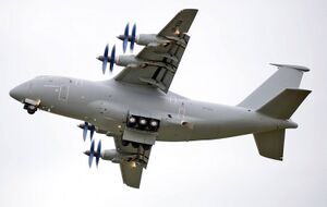
| An FLb-31 shortly after takeoff | |
| Role | Military transport aircraft |
| National origin | |
| Manufacturer | Andreassen Luftfartsselskap |
| First flight | January, 18th, 1995 |
| Introduction | March 15th, 2004 |
| Status | In service |
| Primary user | Trinovantan Air Force |
| Produced | 1991-present |
| Variants | FVå-31 |
The FLb-31 is a Trinovantan four engine heavy tactical airlift military transport aircraft. It was designed to replace the aging FLb-20 tactical airlifter and the FLb-24 strategic airlifter. Though it is designated as a tactical airlifter, its range and payload capacity allow it to function in both capacities. Its capabilities supplement the FLb-27 superheavy strategic airlifter, which remains in service due to its cargo capacity. The FLb-31 is notable for its use of propfan engines.
Though program requirements for what would become the FLb-31 were laid down in the early 1980s, a protracted and troubled development process saw the first complete models being completed in 1991. Problems with engine vibration limited these initial airframes to ground-testing only, with the aircraft achieving its first flight early in 1995. A crash resulting in the total loss of the prototype aircraft as well as the crew occurred in 1997 caused additional delays. Further testing and modifications continued over a long period, until the aircraft was accepted for service in 2004. Despite its extended, problematic development, the FLb-31 has become not only the primary airlift aircraft of the Trinovantan Military, but also spawned many specialized variants that grew the airframe’s capabilities beyond simple cargo transportation.
Design
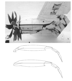
The most immediately notable feature of the FLb-31 is its UF-5 propfan engines. This type of engine, also known as an unducted fan or ultra-high-bypass turbofan, provides similar propulsive efficiency to a turboprop engine at subsonic speeds while possessing thrust performance similar to a high bypass turbofan engine. The UF-5 features a distinct 14 blade contra-rotating propeller with 8 forward blades and 6 rearward blades in a tractor configuration. The majority of the engine’s 119 kN of thrust comes from the forward propellers as the rearward propellers have a lower total surface area and less access to clear air. All of the propeller blades are highly swept scimitar designs with composite blade construction. The high strength composite allows for a light, thin propeller which provides efficient power delivery even at very high rotational speeds. The engine produces its peak thrust of 119 kN at 1000 rpm, which is used during takeoff. At cruising speed, the gearbox maintains a propeller rotation of about 850 rpm. At cruise, the engine has a specific fuel consumption of 11 g/kN⋅s, significantly lower than even some of the best commercial turbofan engines.
One of the challenges of using propfan engines is the high levels of noise they produce. As such, a significant amount of attention was paid to reducing both exterior and cabin noise. The primary means of managing this issue came in the form of modifications to the propeller design, which included changes to the sweep angle, propeller length and the desperation distance between the forward and reward propeller assembly. Though initially noncompliant with Trinovantan and several international aircraft noise regulations, these modifications brought the FLb-31 into compliance with all but the most strict noise restrictions.
As the FLb-31 was intended to replace the STOL FLb-20 tactical airlifter, it was required to have similar short takeoff capabilities. While the FLb-20 could take off within a distance of under 450 meters with a light load, it required a runway of a little over 1000 meters in length to take off with a full fuel load and a 20 tonne cargo. The requirements given for the FLb-31 during its development were more extreme; to be able to take off and land with a 30 tonne cargo load in a distance not to exceed 600 meters. Additionally, it was required the aircraft had to be able to transit a 20t cargo load over a distance of no less than 3000 km under the same conditions. In order to facilitate this demanding level of performance, several design choices were made to emphasize low-speed flight characteristics.
The aircraft’s greatest asset in achieving short takeoff and landing distances was the inclusion of blown controls. This concept uses airflow from the engine’s exhaust to augment the function of the wing and/or certain control surfaces at low airspeeds. The FLb-31 uses both over-wing blowing and flap blowing, allowing for extremely low speed flight for an aircraft of its size. In addition to the blown controls, the FLb-31 uses a relatively thick wing design with a high aspect ratio which provides a high amount of lift at low speeds. This wing design uses a supercritical airfoil in order to reduce what would otherwise be a large amount of drag at the FLb-31’s intended cruise speed. This combination of features allows for both STOL capabilities and a fast, efficient cruising speed.
After the crash of the first prototype aircraft in 1997, great care was taken to ensure that the FLb-31 had predictable and favorable stall characteristics. Of particular concern was sudden low speed stalls resulting from flow separation. This was an unintended consequence of the use of a supercritical airfoil at low speeds, which dampened the characteristic “buffeting” sensation that precedes an imminent stall in most low-speed airfoil designs. Without this warning, as speed decreased and the aircraft’s angle of attack increased, airflow over the wing could suddenly become detached from the surface of the airfoil, resulting in a near-total loss of wing lift. Additionally, the blown controls of the FLb-31 were suspected to have given pilots more confidence that they had full control of the aircraft in the time immediately preceding these sudden stall events. Several years were spent on rectifying these issues through both mechanical means and through electronic feedback from the flight control systems. A combination of more stringent angle of attack limitations, an increased speed threshold for the stall warning indicator, and retractable vortex generators, as well as other more minute changes resulted in the second prototype and the resulting production versions of the FLb-31 having both better pilot feedback and more generally favorable stall characteristics.
On the heavy lift side of the FLb-31’s airlift role, it had to be capable of carrying large cargo loads over long distances when deployed from conventional runways. In this capacity, it had to compare favorably to the FLb-24 strategic airlifter. The FLb-24 was capable of lifting a maximum payload of 41 tonnes. However, its cargo bay was heavily restricted in width and height, and loads of that weight could rarely be fitted into the aircraft. The FLb-31 had a shorter cargo bay, being 22.4 meters in length compared to 31.8 meters of the FLb-24. However, it was much wider (4 meters compared to 3.1 meters) and taller (4.1 meters compared to 2.7 meters). Though the maximum cargo loads of the aircraft are very similar, with the FLb-31 capable of a maximum of 47 tonnes, the FLb-31’s cargo bay is much less restrictive and can more easily accommodate cargo loads closer to this maximum. It can accommodate a fully equipped Vangsness Vandrer main battle tank or two PaVå-35 light tanks with their parachute extraction pallets. In order to accommodate loading of heavy cargo, the FLb-31 is fitted with four electronic hoists. A central deck can also be installed in the cargo hold, allowing the aircraft to function as a two-deck transport for personnel or lighter cargo. In this configuration, the FLb-31 is capable of carrying 300 men, or 200 casualties in stretchers for evacuation.
As a weight saving measure, the FLb-31 makes relatively heavy use of carbon-fiber composites in the airframe, with 25% of the airframe consisting of CFRP composites. These composite components are mostly concentrated in the control surfaces of the airframe and the construction of the tail. The remainder of the aircraft’s construction is largely conventional in both design and materials used.
Operational History
Variants
- FLb-31 - Base Production variant
- FPk-31 - Aerial refueling variant
- FEk-31 - Electronic Warfare variant
- FVå-31 - Gunship variant
Operators
Specifications
General characteristics
- Crew: 3-5
- Capacity: 47,000 kg (103,617 lb) max payload / 300 troops / 200 stretchers
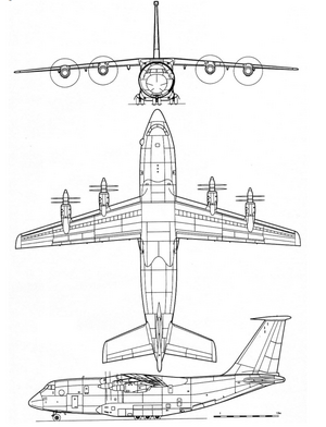
- Length: 40.7 m (133 ft 6 in)
- Wingspan: 44.1 m (144 ft 8 in)
- Height: 16.4 m (53 ft 10 in)
- Empty weight: 66,230 kg (146,012 lb)
- Max takeoff weight: 145,000 kg (319,670 lb)
- Cargo Hold Length: 22.4 m (73 ft)
- Cargo Hold Width: 4 m (13 ft)
- Cargo Hold Height: 4.1 m (13 ft)
- Powerplant: 4 × FEL UF-5 Propfan, 119 kN (27,000 lbf) thrust each @ 1000 rpm
Performance
- Maximum speed: 780 km/h (485 mph; 421 kn)
- Cruise speed: 750 km/h (466 mph; 405 kn)
- Stall speed: 113 km/h (70 mph; 61 kn)
- Range: 1,350 km (839 mi; 729 nmi) with 47,000 kg (103,617 lb) payload from 1,800 m (5,906 ft) runway
- 3800 km (2,400 mi; 2,100 nmi) with 38,000 kg (83,776 lb) payload from 1,800 m (5,906 ft) runway
- 5000 km (3,100 mi; 2,700 nmi) with 30,000 kg (66,139 lb) payload from 1,800 m (5,906 ft) runway
- 7400 km (4,600 mi; 4,000 nmi) with 20,000 kg (44,092 lb) payload from 1,800 m (5,906 ft) runway
- Ferry range: 8,000 km (4,971 mi; 4,320 nmi)
- Service ceiling: 12,000 m (39,000 ft)
- Rate of climb: 24.9 m/s (4,900 ft/min)
- Thrust/weight: 0.333
- Take-off field length: 1,800 m (5,906 ft)
- Landing field length: 2,000 m (6,562 ft)
- Take-off run STOL 30,000 kg (66,139 lb) payload: 600 m (1,969 ft)
- Take-off run STOL 35,000 kg (77,162 lb) payload: 915 m (3,002 ft)


